STM32H723-ADC
STM32H723ZGT6 Development log01 - ADC
What is ADC
The ADC, analog to digital conversion, is a tool to sample the analog values of voltage and transform to digital data. The range of digital data depends on the accuracy of ADC which can be 12bits, 14bits or even 16bits. The choices above are all provided in STM32H723ZGT6 and I personally recommend to use 14bits which mean $ 0-2^{14} $. Above all, ADC is a tool that can sample the analog values and transform to digital stored in STM32 so that we can calculate its real value and process it.
How to quickly start ADC
Due to its wide usage, there are different way to enable ADC and to sample value. We will introduce the mostly used three ways.
ADC + TIM
The first way is to enable a TIMER as a external trigger which enable ADC to sample when the timer count to setting time. It means if you enable the TIM’s Auto-reload, then you will get sample values at the frequency of selected trigger timer. The comprehensive configuration is followed.
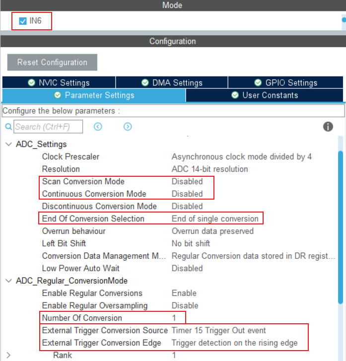
It is easy to configure in this way. Pay attention to the red block I circle! I will comprehensively introduce the use of those configuration so that you can make you own way to enable ADC sample.
- Scan Conversion Mode: Disable when you only use one channel of selected ADC. The “Scan” means Scan Multiple Channel. So if you sample many channels’s value, you need to enable Scan Mode.
- Continuous Conversion Mode: If you don’t use DMA or just sample one single values in one round conversion, you can disable the continuous conversion mode. What the continuous conversion means if you want a list a data, then it will continuously sample the values until fulfill the list.. You can simply understand that it is continuous between two bits.
- DMA Circle: Similar to the continuous conversion mode mentioned above, the DMA circle mode also means continuous conversion. But what is different is that the “continuous” means continuous conversion between two round!. It is said that if ADC finish to fill a list of data like data[128], then it will start next conversion of a list of data Automatically which will cover the data of last round.
- End of Conversion Selection: This configuration contains two choices. If you only use one channel to sample then the “End of single conversion” is fine. But if you use multiple channel to sample then you need to choose “End of sequence conversion” .
- Number of Conversion: The number of conversion is the number of channel that you choose.
- External Trigger Conversion Source: The most commonly used is Timerx Trigger Out event or By software . The first choice is often used when you need to sample at some exact frequency, espacially in signal sample. And the latter simply enable the ADC by a code to start it. When you use the first choice, don’t forget to enable TIMx’s NVIC and configure update event which means if the clock is over than the TIMx will produce a update event and this event can drive the ADC to sample.
- External Trigger Conversion Edge: This usually use default settings.
And the code you should write is also simple.
1 | HAL_ADCEx_Calibration_Start(&hadc1, ADC_CALIB_OFFSET, ADC_SINGLE_ENDED); // accurate adc(must) |
Through experiment verified, the first line of code is necessary, which accurate the value of sample. The rest of code is Start ADC IT and start TIM 15 as trigger source.
And you can read values in ADC Callback function like:
1 | void HAL_ADC_ConvCpltCallback(ADC_HandleTypeDef *hadc) |
Remember to restart ADC if you want to continuous sample. I recommend you write the restart code in Callback function so that you ensure your ADC next conversion starts after the previous done.
ADC + DMA
The second way is one-round sample a list of data with DMA triggered by software. The specific configuration is followed.
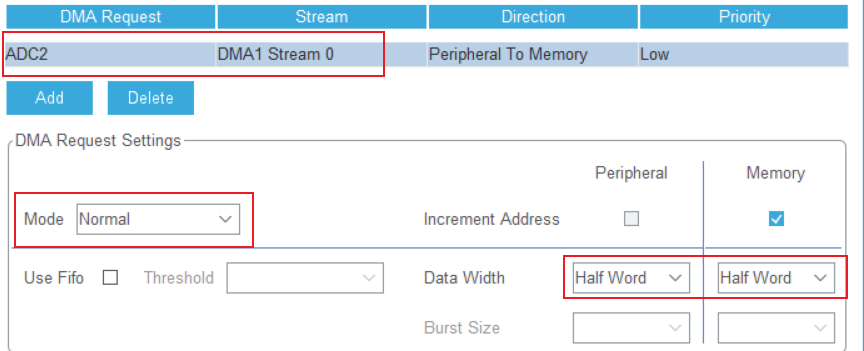
What is special of this configuration is that it only sample one round of a list of data like data[128]. The important point of the configuration is the configuration of DMA which is as followed.
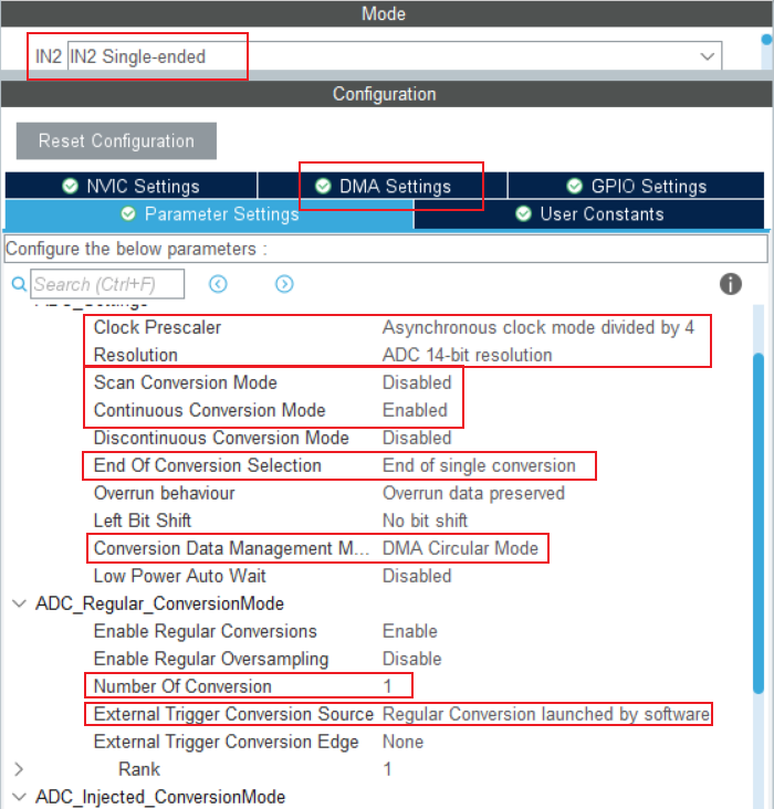
In this way, we use Normal mode of DMA rather than Circle mode which mentioned above means continuously sample round and round, which reveals that when ADC finish sample tasks, you don’t need to restart ADC-DMA for next round of sample because it will start by itself. On the contrary, we configure Normal mode so if you want a new round of sample after last round, you should restart ADC-DMA in the Callback function or somewhere else.
Usually, this function is used when you want to preserve the data and make data process. For an example, you want to sample a list of data of signal and then do FFT or calculate the DC values of it. This way is suitable for you.
ADC+DMA+TIM
In the last part of previous section, we have mentioned about the sample of signal. If you know some basic knowledge of signal sample, you should know the Nyquist Sample theory which says that the sample rate of a signal should be twice larger than the frequency of signal you want to sample so that you can do accurate FFT and recover its wave shape.
So we try to use TIM as an external trigger which we can set the time it trigger. And we configure the Circle mode of DMA which automatically enable ADC sample after one round so that we could get data continuously. The configuration is as followed.
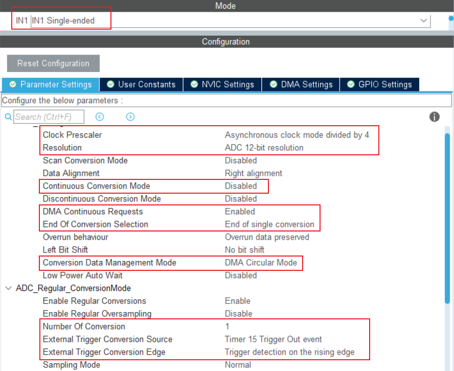
The important part is choosing the TIM update event as a trigger. And the configuration of TIM please look back to Section one: ADC+TIM . Then is the configuration of DMA which is configured as circle mode.
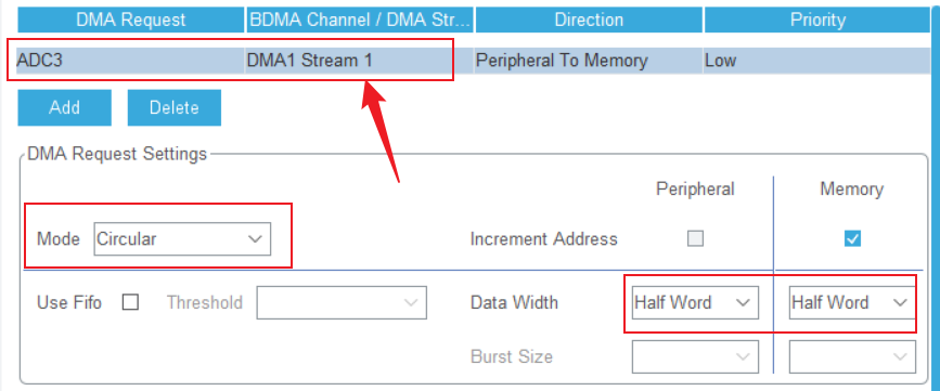
Attention! . You need to ensure the data width is Half-word which is referred to uint16_t . If you want to use Word as you data width then you need to use uint32_t as the size you list of data used.