LanQiao Baseboard Development's log03
LanQiao Baseboard development’s log 03
PWM Input Capture Mode for Frequency and Duty Calculation
What is PWM Input Capture Mode
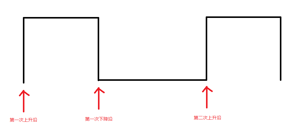
PWM input capture mode, is a special mode of TIM, which is especially useful in frequency measure. But you can’t use it occasionally because it needs a PWM input. Its original theory is below.

How Can We Configure the Input Capture Mode
You should start the TIM input capture and rewrite the callback function. The original theory is when Timer detect the rising edge of PWM signal and then set the TIM counter to zero(Init). When the Timer check the falling edge, the TIM channel will store the counter values. So if Timer detect the second rising edge of PWM, you can read the value of channels which detect the rising edge and the falling edge.
As the counter values refer to the time between two rising edge, which means the time of a whole period, and the values between the first rising edge and falling edge is the time of high level. Based on the knowledge above, you can exactly understand how can we calculate the frequency and duty of PWM.
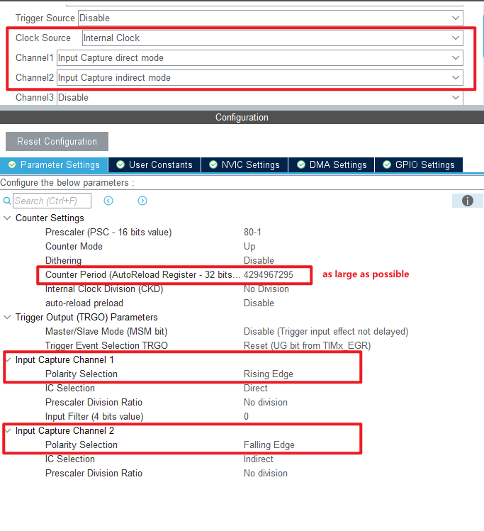
What’s more is that once you get the second rising edge values, you should set the counter of TIM to zeros and restart TIM input capture. And the configuration of TIM is as followed.

First, you need to select the source clock and select two channel, one is direct mode and the other is indirect mode. The counter value should be as large as possible because if the signal frequency is low and the counter value between two rising edge is very large, the second rising edge counter value may be smaller than the first one as the counter reloaded.
Second, you need to configure the indirect mode channel to falling edge to calculate the duty of PWM.
How to Write the Code of PWM Input Capture
Simply, you need to enable the TIM Channel.
1 | HAL_TIM_IC_Start_IT(&htim2, TIM_CHANNEL_1); |
Then, you should rewrite the TIM IC CallBack function. You can define the read-counter values as followed.
1 | bool Is_first_IC1 = 1; // Whether is firstly capture |
And then is the main function.
1 | void HAL_TIM_IC_CaptureCallback(TIM_HandleTypeDef *htim) |
As the theory mentioned above shows, if the callback is from Channel 1(rising edge), read the values and reset the counter values. But Attention! This code doesn’t care about the problem that if the frequency of signal is low and the counter value of the rising edge is smaller than the one of falling edge.
As for the duty, you can simply get it by dividing the rising edge value with the falling edge value.
$$ Freq = \frac{F_{TIM}}{Counter_{fir}}$$
$$ Duty = \frac{Counter_{sec}}{Counter_{fir}} $$
That is the whole content of PWM input capture. Thanks for watching!